> For the complete documentation index, see [llms.txt](https://docs.wcproducts.com/welcome/llms.txt). Markdown versions of documentation pages are available by appending `.md` to page URLs; this page is available as [Markdown](https://docs.wcproducts.com/welcome/greyt/greyt-telescope/assembly-instructions/base-gearbox-flipped/step-6-12.md).
# Step 6-12
{% hint style="success" %}
Vibra-TITE VC-3 Threadmate ([Vibra-TITE](https://wcproducts.com/products/threadlocker)) is recommended on all bolts that thread into a tapped hole.
{% endhint %}
## Step 6
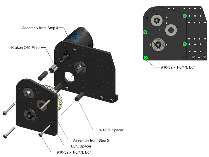
Bolt the two halves of the Gearbox together using the #10-32 x 1-3/4”L bolts. The image down below shows the bolt locations marked out in green.
{% hint style="info" %}
If you are assembling the 1-1/2” Base Gearbox, you can omit the 1/8”L spacers. For those configurations of the Telescope, those bolts will act as pins that hold the 1-1/2” Base Tube in place.
{% endhint %}
## Step 7A
{% hint style="warning" %}
The Drum is **not included** with the Base Gearbox. This Drum is completely optional and can be omitted.
{% endhint %}
The Drum must be cut to the correct length for the Gearbox Configuration you are assembling. The table down below shows the correct lengths for each base tube size.
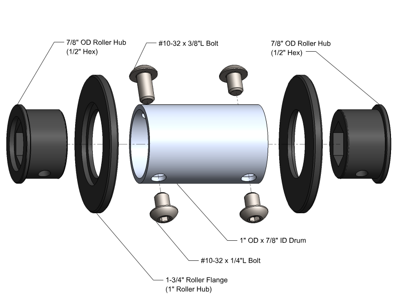
All #10-32 bolts will thread into the 7/8” OD Roller Hubs after they have been pressed into the Drum. The Roller Hubs should be a press fit and may be pressed in with an arbor press.
{% hint style="info" %}
When assembling the drum, it is critical that the hexes for the roller hubs are lined up. In order to do this it is recommended to press one Hub in, and then line up the second Hub with the first Hub using any long piece of 1/2” hex.
{% endhint %}
| Base Tube Size | Drum Length |
| -------------- | ----------- |
| 1.5" | 1.0625" |
| 2" | 1.5625" |
| 2.5" | 2.0625" |
| 3" | 2.5625" |
## Step 7B
{% hint style="warning" %}
If the Drum was omitted in the previous step, the output shaft will need to be drilled out in order to tie the string here.
The 1/16"L Acetal Spacer will need to be printed, the file can be found below.
{% endhint %}
{% file src="/files/apey8QLhyzrkARbhefI5" %}
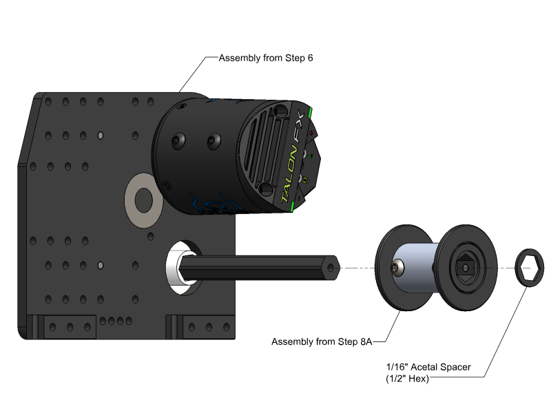
Slide the assembled Drum onto the output shaft. You may have to loosen the #10-32 x 3/8”L bolt in order to do this. Once the Drum is in place, check that the flange does not rub against the Gearbox Plate when the output shaft is spun by hand.
## Step 8
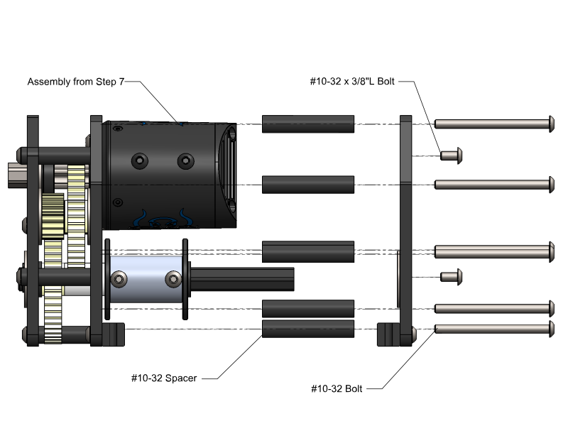
Bolt the two halves of the gearbox together. The bolt locations for the different Gearbox configurations are shown on the following section. When the Gearbox is fully assembled, make sure the Drum Flanges do not rub against the Gearbox Plates when the Output Shaft is spun by hand.
{% hint style="info" %}
Unless otherwise specified, the bolt locations are the same across both the Non-Flipped and Flipped configurations.
{% endhint %}
### Bolt Locations
{% tabs %}
{% tab title="1-1/2" Flipped Gearbox" %}
### 1-1/2” Base Gearbox
The images shown below mark out the bolt locations in green, blue, and orange. These configurations of the Gearbox both use #10-32 x 2”L bolts and 1-1/2”L spacers.
{% hint style="info" %}
The 1-1/2” Base Gearbox does not require the 1/8”L spacers installed in Step 6.
{% endhint %}
{% endtab %}
{% tab title="2" Flipped Gearbox" %}
### 2” Base Gearbox
The images shown below mark out the bolt locations in green, blue, and orange. These configurations of the Gearbox both use #10-32 x 2-1/2”L bolts and 2”L spacers.
{% hint style="info" %}
The 2” Base Gearbox does require the 1/8”L spacers installed in Step 6.
{% endhint %}
{% endtab %}
{% tab title="2-1/2" Flipped Gearbox" %}
### 2-1/2” Base Gearbox
The images shown below mark out the bolt locations in green, blue, and orange. These configurations of the Gearbox both use #10-32 x 3”L bolts and 2-1/2”L spacers.
{% hint style="info" %}
The 2-1/2” Base Gearbox does require the 1/8”L spacers installed in Step 6.
{% endhint %}
{% endtab %}
{% tab title="3" Flipped Gearbox" %}
### 3” Base Gearbox
The images shown below mark out the bolt locations in green, blue, and orange. These configurations of the Gearbox both use #10-32 x 3-1/2”L bolts and an overall 3”L spacer stack up.
{% hint style="info" %}
The 3” Base Gearbox does require the 1/8”L spacers installed in Step 6.
{% endhint %}
{% endtab %}
{% endtabs %}
## Step 9
This step will cover the mounting of either the Friction Brake or the Ratchet & Pawl.
{% hint style="info" %}
This step can be skipped if you plan on using the Telescope without the Ratchet & Pawl or WCP Friction Brake.
{% endhint %}
{% tabs %}
{% tab title="Friction Brake Mounting" %}
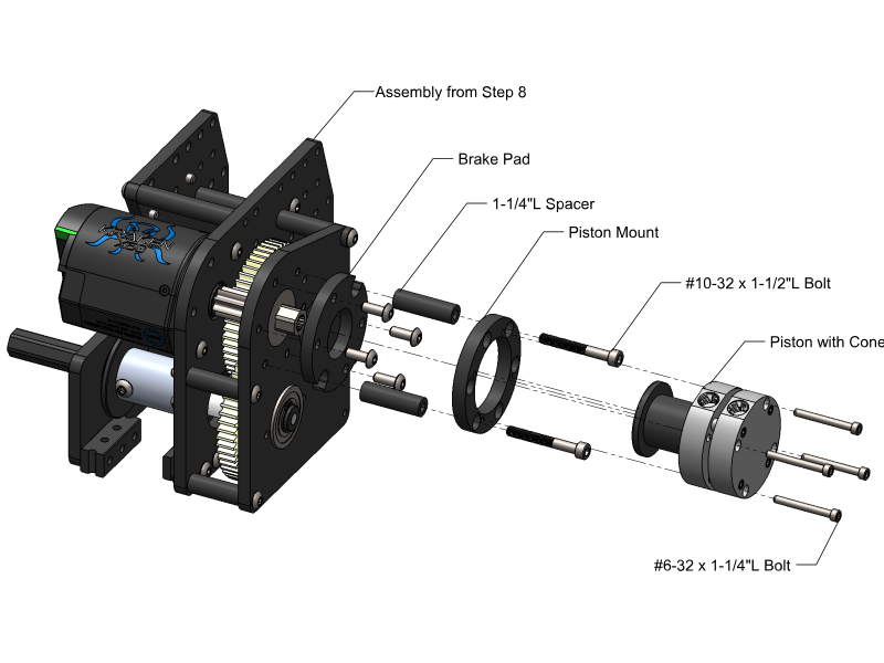
To mount the Friction Brake, first bolt the Break Pad to the Outside Gearbox Plate, then mount the Piston Mount, and finally install the Piston with Cone.
{% hint style="info" %}
Piston and #6-32 x 1-1/4”L Bolt are not sold by WCP.
{% endhint %}
{% endtab %}
{% tab title="Ratchet & Pawl Monting" %}
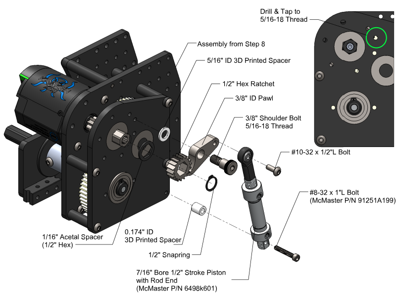
To mount the Ratchet & Pawl, first drill and tap to 5/16-18 the hole the Pawl mounts to. Then mount the Ratchet & Pawl using the parts shown in the image down below. Finally, drill out the mounting hole at the end of the piston with a #18 drill bit and mount the piston once everything else is in place.
{% hint style="info" %}
Piston and #8-32 x 1”L Bolt are not sold by WCP.
{% endhint %}
{% hint style="warning" %}
All Spacers found below will need to be printed, all files can be found below.
{% endhint %}
{% file src="/files/apey8QLhyzrkARbhefI5" %}
{% file src="/files/TebIr3TqRT9odAfYAWT3" %}
{% file src="/files/w2t8GBUeu4bdj6P53hN7" %}
{% endtab %}
{% endtabs %}
## Step 10
Install the 3D Printed Mag Encoder Mount using two #10-32 x 1/2”L bolts. To install the Mag Encoder, remove the board from the case and fit it into the cutout on the 3D Printed Mag Encoder Mount. Use the mounting bolts from the Mag Encoder to attach the sensor. The CANcoder can be used as a drop in replacement.
## Step 11
Apply [Lucas Red "N" Tacky](https://www.lucasoil.com/product/red-n-tacky-grease/) grease to all gears after final assembly to ensure smooth operation and reduce wear during use. Once greased, rotate and spin the shaft to distribute the grease evenly before powering up.
After running gearbox for 15-30 minutes, reapply a light amount of grease. Reapply as needed.
---
# Agent Instructions
This documentation is published with GitBook. GitBook is the documentation platform designed so that both humans and AI agents can read, navigate, and reason over technical content effectively. Learn more at gitbook.com.
## Querying This Documentation
If you need additional information that is not directly available in this page, you can query the documentation by asking a question.
Perform an HTTP GET request on the following URL with the `ask` and `goal` query parameters:
```
GET https://docs.wcproducts.com/welcome/greyt/greyt-telescope/assembly-instructions/base-gearbox-flipped/step-6-12.md?ask=&goal=
```
`ask` is the immediate question: it should be specific, self-contained, and written in natural language.
`goal` is what the user is ultimately trying to achieve, the reason they need the answer. Sharing it helps GitBook give you a better, more relevant answer. A goal is most helpful when it describes the outcome the user wants rather than restating the question. For example, with `ask=how do I create an API token`, a goal like `automate deployments from our CI pipeline` lets GitBook tailor the answer to that use case.
The response will contain a direct answer to the question and relevant excerpts and sources from the documentation.
Use this mechanism when the answer is not explicitly present in the current page, you need clarification or additional context, or you want to retrieve related documentation sections.
 ## Step 7A
{% hint style="warning" %}
The Drum is **not included** with the Base Gearbox. This Drum is completely optional and can be omitted.
{% endhint %}
The Drum must be cut to the correct length for the Gearbox Configuration you are assembling. The table down below shows the correct lengths for each base tube size.
All #10-32 bolts will thread into the 7/8” OD Roller Hubs after they have been pressed into the Drum. The Roller Hubs should be a press fit and may be pressed in with an arbor press.
{% hint style="info" %}
When assembling the drum, it is critical that the hexes for the roller hubs are lined up. In order to do this it is recommended to press one Hub in, and then line up the second Hub with the first Hub using any long piece of 1/2” hex.
{% endhint %}
| Base Tube Size | Drum Length |
| -------------- | ----------- |
| 1.5" | 1.0625" |
| 2" | 1.5625" |
| 2.5" | 2.0625" |
| 3" | 2.5625" |
## Step 7A
{% hint style="warning" %}
The Drum is **not included** with the Base Gearbox. This Drum is completely optional and can be omitted.
{% endhint %}
The Drum must be cut to the correct length for the Gearbox Configuration you are assembling. The table down below shows the correct lengths for each base tube size.
All #10-32 bolts will thread into the 7/8” OD Roller Hubs after they have been pressed into the Drum. The Roller Hubs should be a press fit and may be pressed in with an arbor press.
{% hint style="info" %}
When assembling the drum, it is critical that the hexes for the roller hubs are lined up. In order to do this it is recommended to press one Hub in, and then line up the second Hub with the first Hub using any long piece of 1/2” hex.
{% endhint %}
| Base Tube Size | Drum Length |
| -------------- | ----------- |
| 1.5" | 1.0625" |
| 2" | 1.5625" |
| 2.5" | 2.0625" |
| 3" | 2.5625" |
 ## Step 8
Bolt the two halves of the gearbox together. The bolt locations for the different Gearbox configurations are shown on the following section. When the Gearbox is fully assembled, make sure the Drum Flanges do not rub against the Gearbox Plates when the Output Shaft is spun by hand.
{% hint style="info" %}
Unless otherwise specified, the bolt locations are the same across both the Non-Flipped and Flipped configurations.
{% endhint %}
## Step 8
Bolt the two halves of the gearbox together. The bolt locations for the different Gearbox configurations are shown on the following section. When the Gearbox is fully assembled, make sure the Drum Flanges do not rub against the Gearbox Plates when the Output Shaft is spun by hand.
{% hint style="info" %}
Unless otherwise specified, the bolt locations are the same across both the Non-Flipped and Flipped configurations.
{% endhint %}
 ### Bolt Locations
{% tabs %}
{% tab title="1-1/2" Flipped Gearbox" %}
### 1-1/2” Base Gearbox
The images shown below mark out the bolt locations in green, blue, and orange. These configurations of the Gearbox both use #10-32 x 2”L bolts and 1-1/2”L spacers.
{% hint style="info" %}
The 1-1/2” Base Gearbox does not require the 1/8”L spacers installed in Step 6.
{% endhint %}
### Bolt Locations
{% tabs %}
{% tab title="1-1/2" Flipped Gearbox" %}
### 1-1/2” Base Gearbox
The images shown below mark out the bolt locations in green, blue, and orange. These configurations of the Gearbox both use #10-32 x 2”L bolts and 1-1/2”L spacers.
{% hint style="info" %}
The 1-1/2” Base Gearbox does not require the 1/8”L spacers installed in Step 6.
{% endhint %}


 {% endtab %}
{% tab title="Ratchet & Pawl Monting" %}
To mount the Ratchet & Pawl, first drill and tap to 5/16-18 the hole the Pawl mounts to. Then mount the Ratchet & Pawl using the parts shown in the image down below. Finally, drill out the mounting hole at the end of the piston with a #18 drill bit and mount the piston once everything else is in place.
{% hint style="info" %}
Piston and #8-32 x 1”L Bolt are not sold by WCP.
{% endhint %}
{% hint style="warning" %}
All Spacers found below will need to be printed, all files can be found below.
{% endhint %}
{% file src="/files/apey8QLhyzrkARbhefI5" %}
{% file src="/files/TebIr3TqRT9odAfYAWT3" %}
{% file src="/files/w2t8GBUeu4bdj6P53hN7" %}
{% endtab %}
{% tab title="Ratchet & Pawl Monting" %}
To mount the Ratchet & Pawl, first drill and tap to 5/16-18 the hole the Pawl mounts to. Then mount the Ratchet & Pawl using the parts shown in the image down below. Finally, drill out the mounting hole at the end of the piston with a #18 drill bit and mount the piston once everything else is in place.
{% hint style="info" %}
Piston and #8-32 x 1”L Bolt are not sold by WCP.
{% endhint %}
{% hint style="warning" %}
All Spacers found below will need to be printed, all files can be found below.
{% endhint %}
{% file src="/files/apey8QLhyzrkARbhefI5" %}
{% file src="/files/TebIr3TqRT9odAfYAWT3" %}
{% file src="/files/w2t8GBUeu4bdj6P53hN7" %}
 {% endtab %}
{% endtabs %}
## Step 10
Install the 3D Printed Mag Encoder Mount using two #10-32 x 1/2”L bolts. To install the Mag Encoder, remove the board from the case and fit it into the cutout on the 3D Printed Mag Encoder Mount. Use the mounting bolts from the Mag Encoder to attach the sensor. The CANcoder can be used as a drop in replacement.
{% endtab %}
{% endtabs %}
## Step 10
Install the 3D Printed Mag Encoder Mount using two #10-32 x 1/2”L bolts. To install the Mag Encoder, remove the board from the case and fit it into the cutout on the 3D Printed Mag Encoder Mount. Use the mounting bolts from the Mag Encoder to attach the sensor. The CANcoder can be used as a drop in replacement.
 ## Step 11
Apply [Lucas Red "N" Tacky](https://www.lucasoil.com/product/red-n-tacky-grease/) grease to all gears after final assembly to ensure smooth operation and reduce wear during use. Once greased, rotate and spin the shaft to distribute the grease evenly before powering up.
After running gearbox for 15-30 minutes, reapply a light amount of grease. Reapply as needed.
---
# Agent Instructions
This documentation is published with GitBook. GitBook is the documentation platform designed so that both humans and AI agents can read, navigate, and reason over technical content effectively. Learn more at gitbook.com.
## Querying This Documentation
If you need additional information that is not directly available in this page, you can query the documentation by asking a question.
Perform an HTTP GET request on the following URL with the `ask` and `goal` query parameters:
```
GET https://docs.wcproducts.com/welcome/greyt/greyt-telescope/assembly-instructions/base-gearbox-flipped/step-6-12.md?ask=
## Step 11
Apply [Lucas Red "N" Tacky](https://www.lucasoil.com/product/red-n-tacky-grease/) grease to all gears after final assembly to ensure smooth operation and reduce wear during use. Once greased, rotate and spin the shaft to distribute the grease evenly before powering up.
After running gearbox for 15-30 minutes, reapply a light amount of grease. Reapply as needed.
---
# Agent Instructions
This documentation is published with GitBook. GitBook is the documentation platform designed so that both humans and AI agents can read, navigate, and reason over technical content effectively. Learn more at gitbook.com.
## Querying This Documentation
If you need additional information that is not directly available in this page, you can query the documentation by asking a question.
Perform an HTTP GET request on the following URL with the `ask` and `goal` query parameters:
```
GET https://docs.wcproducts.com/welcome/greyt/greyt-telescope/assembly-instructions/base-gearbox-flipped/step-6-12.md?ask=